


ALU Frames are lightweight, durable and high capacity aluminum shoring frames. Aluminum has proven to withstand job site wear and tear, enabling a longer period of use.
ALU Frames fulfill the optimum requirements for capacity, weight, durability and handling during construction.
ALU Frames achieve reduction in the overall cost of forming, based on increased productivity and decreased physical exertion of construction workers.


Part No. 1043
Size: 4’-0” x 3’-0” (1.22m x 0.91m)
Weight: 19.0 lb (8.6 kg)
Cross Brace Pin Spacing: 2’-0” (0.61m)

Part No. 1044
Size: 4’-0” x 4’-0” (1.22m x 1.22m)
Weight: 22.0 lb (10.0 kg)
Cross Brace Pin Spacing: 2’-0” (0.61m)

Part No. 1045
Size: 4’-0” x 5’-0” (1.22m x 1.52m)
Weight: 28.5 lb (13.0 kg)
Cross Brace Pin Spacing: 4’-0” (1.22m)

Part No. 1046
Size: 4’-0” x 6’-0” (1.22m x1.82m)
Weight: 32.0 lb (14.5 kg)
Cross Brace Pin Spacing: 4’-0” (1.22m)

Part no. 1048
Size: 4′-0 x 8′-0 ( 1.22m x 2.44m)
Weight: 48.9 lb (22.2 kg)
Cross Brace Pin Spacing: 2’/4’/6′ (0.61m,1.22m,1.83m)
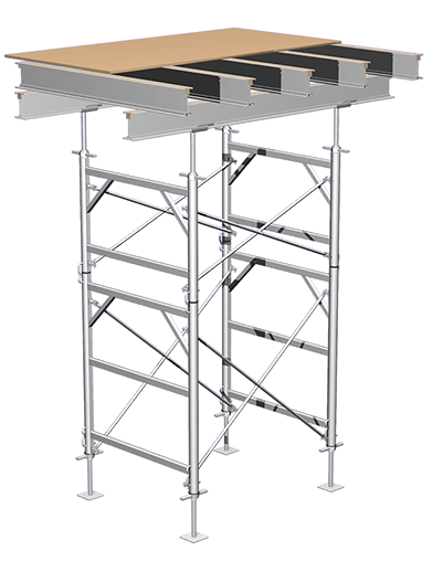
National Forming Systems Inc. HTS Frame was developed as a result of a long term study of the construction need to accommodate optimal demands between:
High Capacity
Durability
Easy Handling
The result is an economical and time saving HTS Shoring System.


900 x 2700mm | 900 x 1800mm | 900 x 900mm

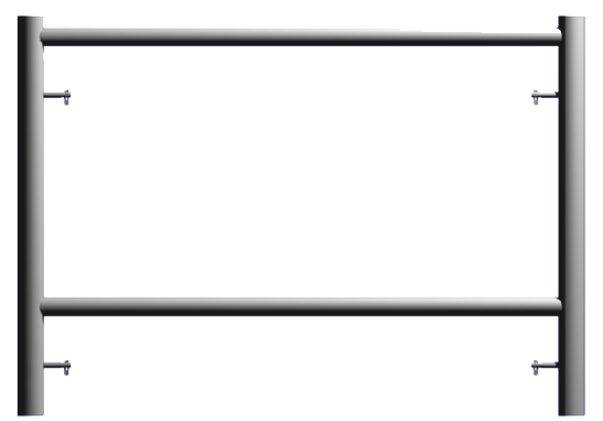
Part No. 2042
Size: 4′-0″ W x 2′-0″ H (1.22m x 0.61m)
Weight: 24.00 lb (10.90 kg)
Single Drop Lock

Our lightweight Modudeck system consists out of the following main components:
Panels including the plywood are available in standard sizes 180x60cm, 120x60cm and 60x60cm, Main Beams with lengths 240cm, 180cm, 120cm, Props which can be Mega Shores or props from our DIN EN 1065 program.
By using the system dropheads which are being mounted onto the props, early striking can be utilized to move the panels and beams already to the next use on site, while the props are still fully engaged and supporting the slab.


Mega Shores represent a new generation of single support shoring equipment. They were developed as a result of demand for an economical, lightweight and versatile shoring system that could substantially save man hours and increase productivity.
Forming area ratio to man hours is cut in half as Mega Shore capacity is almost double than other single prop equipment with low Mega Shore weight factor to capacity.
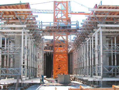
Mega Shores are made of aluminum alloy with base plates welded to one end of the inside and outside tube. Outside tube is powder coated while the inside tube is plain aluminum with four self-cleaning treaded wings and free-running cast iron nuts.
Mega Shores combined with lateral bracing can be used as shoring tower having a higher capacity than as a single support. Outside and Inside Tube each has four opposite slots for connection to lateral bracing members. Lateral bracing can be done with Cross Braces or Bracing Frames connected to the outside or inside tube with NFS Beam.
Cross Braces

Part No. 1043
Size: 4’-0” x 3’-0” (1.22m x 0.91m)
Weight: 19.0 lb (8.6 kg)
Cross Brace Pin Spacing: 2’-0” (0.61m)
Bracing Frame

Part No. 1044
Size: 4’-0” x 4’-0” (1.22m x 1.22m)
Weight: 22.0 lb (10.0 kg)
Cross Brace Pin Spacing: 2’-0” (0.61m)
4 x 5
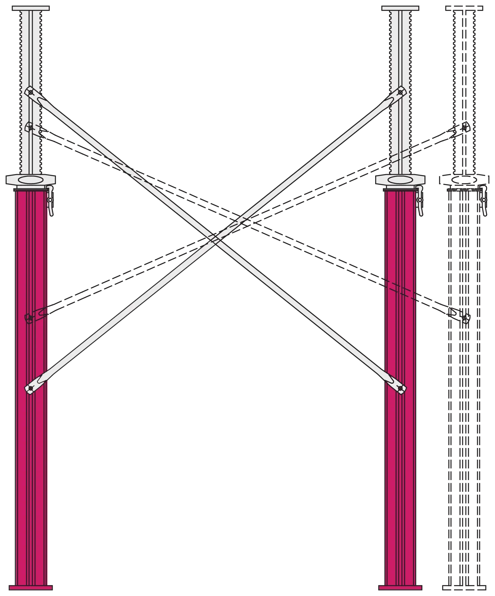
Spacing between Mega Shores is not predetermined by size of brace.

Part No. 1043
Size: 4’-0” x 3’-0” (1.22m x 0.91m)
Weight: 19.0 lb (8.6 kg)
Cross Brace Pin Spacing: 2’-0” (0.61m)

Part No. 1044
Size: 4’-0” x 4’-0” (1.22m x 1.22m)
Weight: 22.0 lb (10.0 kg)
Cross Brace Pin Spacing: 2’-0” (0.61m)

Spacing between Mega Shores is not predetermined by size of brace.
A-Frame Fly Form System is a type of concrete forming widely used for supporting cast-in-place concrete slabs in high-rise construction.
The method of table relocation gives this concrete forming system the name A-Frame Fly Form System and the tables, A-Frame Fly Form Tables.
A-Frame Fly Form design meets the demand of today’s challenging environment that requires a flexible and time saving construction system.
It is fully adaptable to the configuration and shoring height of a slab and much lighter and cost efficient compared to conventional trusses.
Variable Capacity
The unique variable spacing between A-Frames controls the capacity of the truss. When A-Frames are moved close to each other, truss capacity increases, supporting the heavier concrete weight. Alternately, when A-Frames are moved apart, truss capacity decreases for lighter concrete weight.


Capability of A-Frame to connect to top and bottom truss chord at any required location for truss lengths, from 15ft to 100ft, and capability to position Hinged Table Leg at any location of Bottom Chord is the key to capacity and overall effectiveness of A-Frame Truss structure.

HV Main and Secondary Beam features:
Lightweight aluminum members.
Designed for easy, safe and fast handling.
Timber nailers included in all members.
Exceptionally durable.
Standard Main Beam: 5′ 7″ @ 30.4 lbs. (1.7 m @ 13.8 kg)
Fillers: 3’9″ @ 20 lbs (1.15 m @ 9.4 kg)
Cantilevers: 11’6″ @ 63 lbs. (3.5 m @ 28.6 kg)
Standard Secondary Beam: 5′ 7″ @14 lbs. (1.7 m @ 6.2 kg)
Fillers: 3’9″ @ 7.8 lbs. (1.15 m @ 3.5 kg)
HV Shores
Durable, telescoping steel shores
Supports slabs in excess of 12″ (300 mm)
Height Range: 7’0″ – 18’10” (2.15 m – 5.75 m)

HV Main and Secondary Beam Components:
Hot–dip galvanized.
Attaches to Post Shores with 2 bolts.
Includes quick–release disc wedge.
Allows stripping in tight quarters.

Main Beam
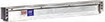

Drophead
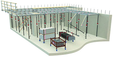
Accommodates framing irregularities by rotating members and eliminating cutting or lapping.


